


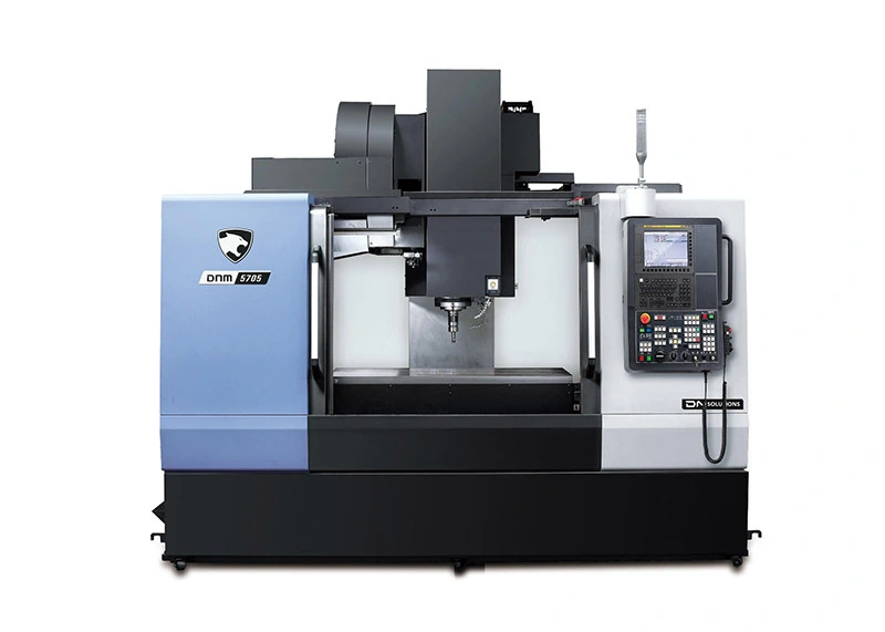
3 Axis Vertical Machining Center Vertical CNC Machine DNM5705
The DNM series has higher production efficiency and more reliable configuration. placement and structure. The DNM series adopts high-rotation and high-rigidity design.
Introduction
● World standard, Global bestseller for high productivity, Vertical Machining Center
The DNM series has higher production efficiency and more reliable configuration.placement and structure. The DNM series adopts high-rotation and high-rigidity design.
Design concept, equipped with direct-coupled spindle and roller guide rail, to provide customers with Provide users with the best processing experience. DNM series processing empty
The space is expanded to be the largest among machine tools of the same class to cope with diversification.
Main performance
Spindle Power-Torque Diagram
Working Desk Size
Machine tool dimensions
| DNM series (left or right chip conveyor) top view | Side view | |||||
| Model | A(L) | B | C | D(W) | E(H) | F |
| DNM5705 | 2221 | 3349 | 1010(398) | 3145 | 2985 | 883(440) |
Maximum machine length (with electrical cabinet door and rotating operating panel)
Width increased to accommodate side chip conveyors [ ] indicates the additional width required to accommodate a spiral chip conveyor.
The height from the ground to the chip outlet [ ] indicates the height required to install a spiral chip conveyor.
| DNM series (rear chip conveyor)top view | side view | ||||||
| Model | A(L) | B | C | D(W) | E(H) | F | G |
| DNM5705 | 2221 | 458 | 3349 | 650 | 3105 | 2985 | 883 |
To accommodate the additional length required for the chip conveyor on the rear side.
Maximum machine length (with electrical cabinet door and rotating operating panel)
Additional space required to accommodate rear chip conveyor. The height from the ground to the chip exit.
Basic parameters
| Project | unit | DNM 5705 | |
| Travel | X-axis | mm | 1050 |
| Y-axis | mm | 570 | |
| Z-axis | mm | 510 | |
| Distance from spindle end face to work surface | mm | 150-660 | |
| The distance between the spindle center and the column guide rail | mm | 618 | |
| Working table | Working table size | mm | 1300x570 |
| allowable load | kg | 1000 | |
| T-slot | 4-125X18H8 | ||
| Spindle | Maximum spindle speed | r/min | 8000(12000) |
| Spindle taper | ISO#40 7/24 taper | ||
| Maximum torque | N.m | 117.8 | |
| Feed rate | Rapid movement speed (X/Y/Z) | m/min | 36/36/30 |
| cutting feed rate | Mm/min | 1-15000 | |
| Automatic tool exchange | Tool handle type | BT40 | |
| Tool magazine capacity | Ea. | 24 | |
| Maximum tool diameter | mm | Ø80 | |
| Maximum tool diameter of adjacent space mm Ø | mm | Ø125 | |
| Maximum tool length | mm | 300 | |
| Maximum prop weight | kg | 8 | |
| Tool selection method | random storage | ||
| Tool changing time (knife-knife) | s | 1.2 | |
| Tool change time (cutting to cutting) | s | 3.2 | |
| motor | Spindle motor | kW | 11/18.5 |
| Feed motor (X/Y/Z) | kW | 1.8/1.8/3 | |
| power supply | Power supply (rated power) | kVA | 30 |
| Box capacity | Coolant tank capacity | L | 380 |
| Grease capacity | L | 0.7 | |
| Machine size | Machine height | mm | 2985 |
| Machine tool area (length x width) | mm | 3110 x 2413 | |
| Machine weight | kg | 6500 | |
| Standard configuration | Options configuration |
| 10.4" Color TET LED Assembly and operating tools Cooling box and chip tray Safety door interlocks Standard cooling system Mount 4th axis preparation Cam ATC (30/40 knives) Chip conveyor and chip collector Minimum quantity lubrication Oil cooler* Built-in spiral chip conveyor Working status lights (red, yellow, green) Portable MPG Splash-proof sheet metal Work lights (LED lights) X, Y, Z absolute pulse encoder |
4th axis preparation Cam ATC (30/40 knives) Chip conveyor and chip collector Minimum quantity lubrication Oil cooler* Oil skimmer Spray cooling system Test stick Water outlet from spindle center Oil mist collector |
NC equipment specifications
| Axis control | Number of programs that can be stored | 1000ea | |
| Number of control axes | 3 axes | Select block to skip | |
| Control the number of axes simultaneously | Multiple jumps | ||
| Positioning (GOO)/linear interpolation (G01) | 4 axes | macro executor | |
| Arc interpolation (G02, G03) | 2 axes | Select stop | M01 |
| Control shaft disassembly | Part program storage length | 2M | |
| backlash compensation | Program protection | ||
| Emergency stop/overtravel | Program number | 04 digits | |
| HRV control | HRV2 | Sequence number | N8 digits |
| location tracking | Program stop/end | M00,M02,M30 | |
| Incremental System C | isxc | Programmable data input | Tool offset and workpiece offset are input by G10, G11 |
| Minimum instruction increment | 0.001/0.0001mm/inch | subroutine call | 10 levels of nesting |
| Minimum input increment | 0.001/0.0001mm/inch | paper tape code | ELA RS422/ISO840 |
| Machine locked | All axes/ Z axis | Thread cutting | |
| mirror | All axes | Local/machine coordinate system | G52/G53 |
| Storage type pitch error compensation | Program cycle start | ||
| Stored trip check 1 | Workpiece coordinate system | G54-G59 | |
| Limit switch | Add workpiece coordinate system | ||
| Absolute pulse encoder | Other functions (operation, setting and display, etc.) | ||
| Interpolation & feed function | Return to 3rd/4th reference point | ||
| Return to second reference point | G30 | Additional workpiece coordinate system | G54,1P1-48(48 pairs) |
| Return to the third and fourth reference points | Show actual speed | ||
| Arc interpolation | G02,G03 | Coordinate system rotation | |
| Cylindrical interpolation | G07,1 | Embedded Ethernet | |
| Nano interpolation | USB memory interface | ||
| Inverse time feed | DNC operation based on memory card | ||
| Feed pause | G04 | External data input | |
| Exact way to stop | G09,G61 | Multi-language display | |
| Feed speed override (10% unit) | 0-200 | RS232 interface (for2ch) | |
| spiral interpolation | programmable mirror | ||
| JOG magnification (10% unit) | 0-200% | CS contour control | |
| Automatic corner magnification | G62 | External key input | |
| Automatic corner deceleration | FS10/11 paper tape format | ||
| Balanced cutting | Alarm display | ||
| Rapid feed bell-shaped acceleration and deceleration | Alarm history display | ||
| Linear interpolation | G01 | Automatic corner magnification | G62 |
| Manual feed per revolution | clock display | ||
| Bell-shaped acceleration and deceleration before β-type interpolation | Coordinate system rotation | G68,G69 | |
| smooth interpolation | Start running/feed hold | ||
| Handwheel feed magnification | 0.1/0.01/0.001mm | PMC alarm information display | |
| Cancel magnification | M48/M49 | dry run | |
| position | G00 | graphic display | Tool path display |
| Rapid feed rate | F0(fine feed)25/50/100% | Help function | |
| Return to reference point | G27,G28,G29 | High speed skip function | |
| jump over | G31 | Current location display | |
| Feed per minute | Mm/min | advance control | G08 |
| AICC | 40(DNM605W) | display device | 10.4" color LCD/MDI |
| AICC II | pre-read200(except dnm605W) | Memory card interface | |
| Processing condition selection | Operation function | ||
| Interpolation pitch compensation | Operation history display | ||
| High-speed and high-quality machining software package | DNM605W option | Any chamfer/corner R | |
| Spindle & M code function | Polar coordinate command | G15/G16 | |
| M code function | M3 digits | program restart | |
| Spindle orientation | Programmable data input | ||
| Spindle serial output | Run time and parts count display | ||
| Spindle speed function | 55 digits | scaling | G50,G51 |
| Spindle speed magnification | 50-150% | Search function | Sequence number/program number |
| Spindle output switching | Self-diagnosis function | ||
| Rigid tapping retraction | Servo setting screen | ||
| Rigid tapping | single step | ||
| Tool function | One-way positioning | G60 | |
| Tool radius compensation | G40,G41,G42 | Stored trip check 2 | |
| Tool offset quantity | 400 pairs | Ethernet functionality | |
| Tool length compensation | G43,G44,G49 | Automatic data backup | |
| Tool length measurement | Dynamic graphics display | ||
| Tool life management | EOP (Easy Operation Package) | ||
| Tool life management extension | Tool load monitoring | ||
| Tool function | T8 digits | Select specifications | |
| Tool length offset | Additional controllable axes | 5 axes in total | |
| Tool compensation memory C | Shape and wear are stored separately, and length compensation and radius compensation are separately stored. Don't save |
Manual wheel return | |
| Tool position offset | G45 x G48 | Operation guide i | |
| Program & Editing Functions | Operation guide 0i | ||
| Absolute/incremental programming | G90/G91 | text engraving | |
| Automatic coordinate system setting | CF card (2GB) | ||
| Background editing (background editing) | PROFIBUS-DP | ||
| Processing cycle | G73,G74,G76,G80,G89,G99 | PROFINET | |
| R programming circular interpolation | CC-LINK | ||
| User software capacity | 6M | Adding the number of workpiece coordinate system groups | G54.1 P1 X 300 (300 pairs) |
| Append user macro variables | #100X@199,#500 X #999 | Inclined plane indexing command | G68.2 |
| 10 times the input unit | Inclined surface indexing command function | G68.2 TWP command on guidance window | |
| RS-232C interface | Multi-spindle control | ||
| USB interface | Three-dimensional rigid tapping return | ||
| Imperial/Metric conversion | G20/G21 | Jerk control | |
| mark skipped | Data server (1GB PCMCIA card) | ||
| Maximum command value | ±99999.999mm(±9999.9999 inch) | Fast Ethernet board |
Main specifications
| Project | Unit | DNM5705 |
| Axial travel (X/Y/Z) | mm | 1050/570/510 |
| working desk size | mm | 1300X570 |
| Maximum load of workbench | kg | 1000 |
| Maximum spindle motor power | kw | 18.5/11 |
| Maximum spindle speed | R/min | 8000(12000) |
| Maximum spindle torque | N.m | 117.8 |
| Tool storage capacity | Ea. | 24 |
| hilt | BT40 | |
| Rapid feed speed (X/Y/Z) | m/min | 36/36/30 |
SOUTH lathe is a professional CNC machine manufacturer of turning-milling drilling, tapping and carving combined machine tool.
Contact Us
![]() +86 13928187729
+86 13928187729
![]() +86 13928187729
+86 13928187729
![]() manager@southlathe.com/ js_john@vip.163.com
manager@southlathe.com/ js_john@vip.163.com
![]() No.3 Huafu Road, Bianjiaojuweihui, Ronggui town Shunde Foshan City, Guangdong Pronvice China.
No.3 Huafu Road, Bianjiaojuweihui, Ronggui town Shunde Foshan City, Guangdong Pronvice China.